Sunday, August 23, 2015

Multifractals in the first occurrence of each k = {0,1,2,3,4,5,6,7,8,9} in the values of f(n)=sqrt(n)−trunc(sqrt(n))

Learning how to generate the Mandelbrot set, I came across the definition of the "escape condition" which is the one that decides the color that is applied to each point of the plane where the Mandelbrot set is being calculated. This is a mirror of the question at MSE about the observation I did below.

I tried to use that "escape condition" concept in a test regarding the fractional part of sqrt(n), f(n)=sqrt(n)−trunc(sqrt(n)) truncated to 7 decimals. The algorithm finds for all f(n) the first occurrence of a specific value k={0,1,2,3,4,5,6,7,8,9} in the decimals of f(n). For instance 0.0123456 has its first decimal value k=0 in position 1, in other hand 0.1230320 has its first decimal value k=0 in position 4. If it is not found, the escape value will be the maximum possible value, 8. As in the Mandelbrot set depending of the escape value, a different color will be used.

A) First I have organized the natural numbers in the positions a_xy of a plane as follows:

a_n0=n^2
a_n1=(n^2)+1
a_n2=(n^2)+2
a_n3=(n^2)+3
...
a_ni=(n^2)+i
while i<n

In the first file there are squares, in the second squares + 1, in the third squares +2, etc. while the values are less than the next square: 

B) Then each element a_ni is replaced by f(a_ni)=sqrt(a_ni)−trunc(a_ni),  truncating up to 7 decimals. 

C) Finally, for all f(a_ni) now it is possible to find the first occurrence of for instance k=0 in f(a_ni). It is found starting from the upper decimal value. The position where it is found is the "escape position", and each position will have its own color. 

This is the plotting of colors of each escape position for the algorithm when looking for the first occurrences of k=0 in f(a_ni):


Same exercise for the first occurrences of k=1:


They are very similar, but they are not the same. It seems that there are star-like patterns acting like local "attractors" (please excuse me if I abuse of the terminology).

This is an animated image with the same graph when looking for the first k=0, then k=1... up to the first k=9. Same color in the animation means that the first occurrence of k is in a same specific position. It is reduced to fit the screen, when clicking in the image it is possible to see it correctly:


When looking to the animation, it seems that the first occurrences of each type of k are "rotating" around the "local attractors". E.g. at column n=500 is easy to observe the rotation.

It seems that there is a symmetry in the background between the upper side and the lower side of the bisection of the triangle that has (0,0) as the bisection vertex. The direction of the "rotation" explained above is inverted between both sides of the bisection (the upper part "rotates" to the right, and the lower part to the left), but the mapping of colors in both sides seem to be initially the same one.

I have plotted the images with a gray scale gradient, so now it is possible to see more details of the above rotating picture:


The following animation is the search of the position of the first decimal value k=0 in the fractional digits obtained by applying the functions f(n)=n^t−trunc(n^t), where t belongs to the interval [0.49995..0.50006] and each frame is increasing by 0.00001. The pattern "bends" in XY and the background star-like patterns are relocated depending on the slight changes of t. 


Finally, as +XY is symmetric in −XY this is how it looks like the complete picture, without the restriction regarding the values being less than the next square, so it fills the XY plane completely:


This is what I have found so far, there is a comment at my MSE question that explained that these patterns are multifractals, and there is a page with similar star-like patterns appearing in the representation of modular arithmetic products. That is quite interesting, because initially my graphs are not directly related with modular arithmetic, but if the same patterns arise, then there could be a link between modular arithmetic and the first occurrence of a specific digit in the fractional part of sqrt(n).

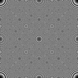
UPDATE: it seems that my algorithm is producing Moiré patterns. I did the same test using the fractional part of n/m and a similar pattern appears. Using the color code in the first graphs should avoid that effect, indeed the pattern is there independently of the zoom (so it would not be Moiré if I can see the pattern independently of the zoom) but in the case of the polar coordinates, it seems too similar to this. Maybe the examples of the modular arithmetic website are also Moiré patterns, the circular examples in the site look exactly like this. 

Once I found the relationship with the Moiré patterns, just found at MSE a question about the same topic, so somehow the algorithm I did and the modular arithmetic calculations both seem to generate Moiré patterns. 

Wednesday, August 12, 2015

Vizualizing some modulo-n series

The following is an algorithm able to calculate some generic modulo-n relationships in a very visual way:

a(n) = total number of vertices of a polygon (n-gon) that are a "final vertex" of aclass of curve defined at integer values which hops from one value to another (please see images below for reference), and is defined by the following algorithm:

(1) Define counter c=1.

(2) Start at any desired vertex and advance clockwise c vertices.

(3) Mark the current vertex as a "final vertex".

(4) c=c+1.

(5) Starting from the last final vertex, count clockwise up to c again, and mark that vertex as a "final vertex" as well.

(6) Repeat from (4).

It is cyclical: after some repetitions of steps (4)-(6), the cycle along the vertices is repeated and it is possible to count how many vertices of the n-gon contain a "final vertex" mark.

For instance these are some series that can be calculated by using the algorithm: 

1. When the n-gon is a triangle, it generates OEIS A117484 (Number of triangular numbers mod n) 

2. When the n-gon is a square, it generates OEIS A047452 (Numbers that are congruent to {1, 6} mod 8).

3. When the n-gon is a pentagon, it generates OEIS A047219 (Numbers that are congruent to {1, 3} mod 5).

4. When the n-gon is an hexagon, it generates the sequence of numbers that are congruent to {1,10} mod 12) (not registered at OEIS).

etc. (upper sequences are not registered at OEIS).

The main point is that the algorithm visualizes the bouncing patterns of the modulo-n series, this is how it looks like (this is the representation of the n-gons 3 to 14, 16, 17 and 27):


The more vertices are added, the easiest it is to visualize the bouncing patterns.

For instance, this is the basic one, the triangle (3-gon):


As it is very plane (3 vertices) it is not so easy to observe the bouncing, but in the case of the 27-gon the pattern is clear:


I think that the algorithm makes easier playing with the modulo-n properties, for instance somebody not familiar with modular arithmetic can initially play with these patterns and visualize the results, and then it can be explained in terms of modular arithmetic what is seen in the patterns.

Tuesday, July 28, 2015

Playing with the Chaos Game: non-Euclidean Sierpinski attractor in spherical coordinates

In my former post about The Chaos Game I did a non-Euclidean Sierpinski attractor by using polar coordinates in the XY plane (2D). Now I have tried to make a new "flavor" by using spherical coordinates in the XYZ region (3D). 

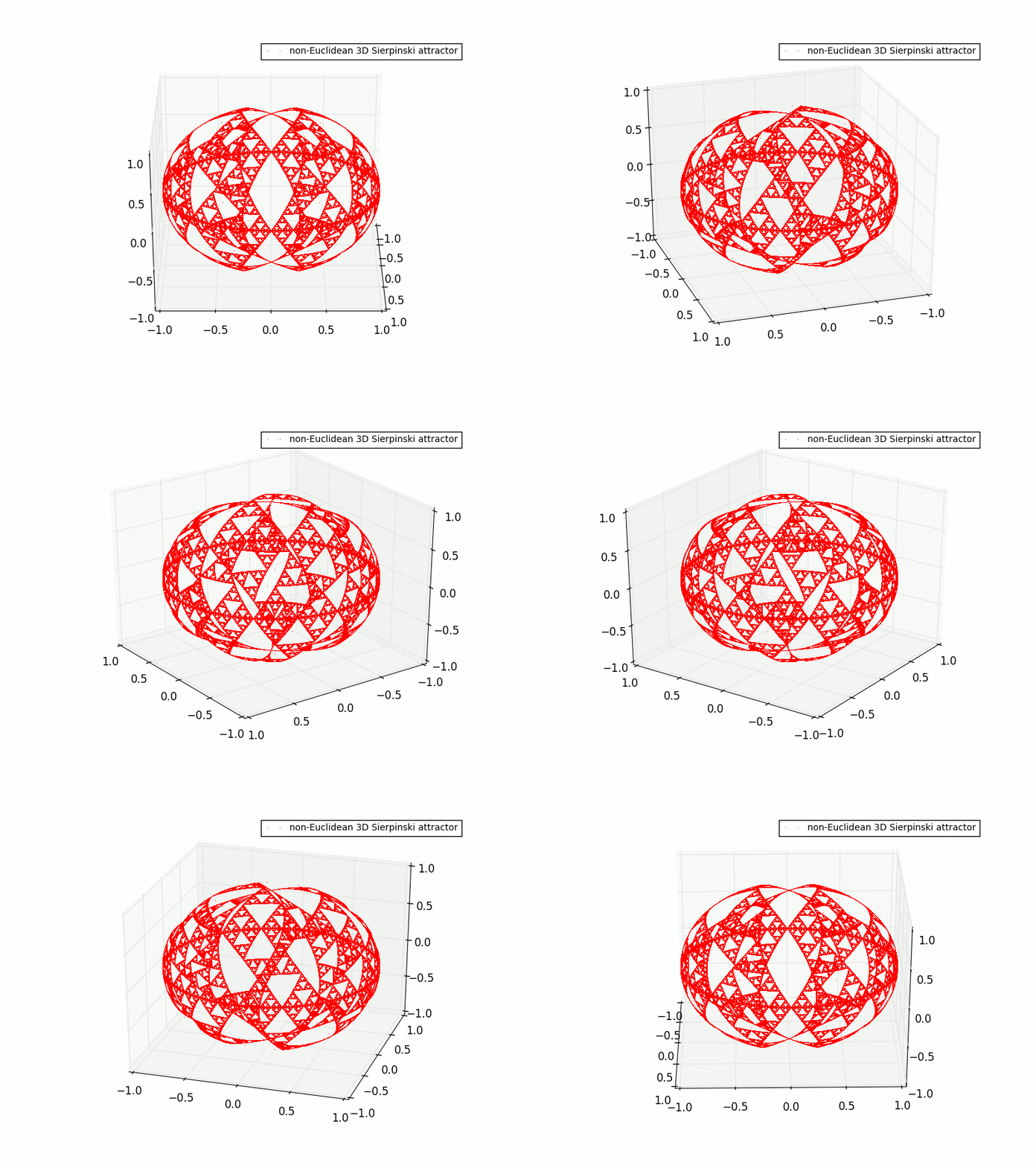
In this case, I have divided the sphere into 8 quarters, and the Sierpinski attractor is generated in the surface of a quarter of the sphere and the rules of the Chaos Game regarding how to manage the angles are exactly the same rules as for the polar coordinates version of my former post, but with one more dimension (in other words, one more angle to play with). Specifically the three attractor points are at A=(phi=0,theta=0,r) (east of the XY plane), B=(phi=3PI/2,theta=0,r) (south of the XY plane) and C=(phi=7PI/4,tetha=PI,r) (north of the XZ plane). This produces a non-Euclidean spherical Sierpinski attractor in this fashion:


The next step is just replicating the pattern symmetrically on the surfaces of the rest of quarters of the sphere, and this is the result! (it is an animated gif, it could take a little bit to load):


Two more views:


I am really very happy with the results! The spherical symmetry is beautiful. It is easy to do bad calculations when working with polar and spherical coordinates. If possible I will try to add more "flavors" of The Chaos Game. If somebody is interested in the Python code, please just let me know!

Wednesday, July 22, 2015

Hobbymath's wanderings #9

A random walk through fractal dimensions.

Wikipedia: the Chaos Game.

Wolfram: the Chaos Game.

About the Chaos Game.

Examples of Iterated Function Systems.

The Beauty of Roots (polynomials of degree ≤ 5).

Barnsley Fern.

Superfractals: the Chaos Game.

Adding a little more chaos to the Chaos Game.

The Chaos Game in polar coordinates: a nice non-Euclidean Sierpinski attractor

I am learning the basic concepts about the Chaos Game (I did a previous question about the same topic at MSE here), the method to create fractals elaborated by professor Michael Barnsley.

The basic example (euclidean-cartesian) requires three attractor vertices, ABC, and as Wikipedia explains: "The fractal is created by iteratively creating a sequence of points, starting with the initial random point, in which each point in the sequence is a given fraction of the distance between the previous point and one of the vertices of the polygon; the vertex is chosen at random in each iteration."

The sequence of points (x,y) will produce the pattern of the Sierpinski attractor:


When I saw that construction, I wondered if there was another way of obtaining an attractor with two variables and three attractor points, and thought about polar coordinates. I did not find any references, so I did my own version of the Chaos Game for polar coordinates.

In this version, the points are (theta,r) (the angle in radians and the radius). And the three attractor points are A=(0,0), B=(5PI/4,1) and C=(7PI/4,10^4).

This is the algorithm I have implemented:


 And this is the result for 10^7 iterations, a nice Sierpinski attractor:


The Sierpinski attractor appears, but there is a distortion due to the use of polar coordinates. In the case of the polar coordinates the point (theta, r) has two options to arrive to the attractor point: using the clockwise angle or the counterclockwise angle. Only selecting the shortest path (in this case the smallest angle of both options) the Sierpinski attractor is shown. It looked like a (sorry if I am not using the appropriated words) "non-Euclidean" Sierpinski attractor.

This is another example locating the attractor points in the same axis: A=(0,0), B=(PI-PI/8,1) and C=(7PI/4,10^4).


I wondered if, according to the results, can be said that the Sierpinski attractor in the polar coordinates pattern is a "non-Euclidean" version of the attractor (or it is only a "Euclidean" distortion of the original attractor). Fortunately a fellow from MSE confirmed that it is fair to say that is is a non-Euclidean version! Here is the link to my question and the answer. I am very happy because I think this might be the first version of the Chaos Game in polar coordinates showing the Sierpinski attractor in a non-Euclidean "flavor", I could be wrong but initially I did not find it in Internet!

Monday, July 20, 2015

An interesting sequence obtained from an orbits simulator: Fibonacci (II)

In the previous post I wrote an orbit simulator that produces a very intriguing sequence. I am still reviewing it, and still did not see any special property of it, but using the same orbits algorithm and instead of  using the sequence of natural numbers, using Fibonacci numbers the results are much more interesting!

Here are the results of the first terms, when the sequence is the Fibonacci numbers, due to the relationship of the Fibonacci terms, only two orbits are generated. A third orbit will never be possible!


Observing the two orbits it is easy to see that the odd terms of the first orbit divide the odd terms of the second orbit in the same position. And here is the surprise, when dividing the second orbit terms by the first orbit terms, the appearing sequence is:

{1, 7, 29, 123, 521, 2207, 9349, 39603, 167761, 710647, 3010349, 12752043, 54018521, ...}

Which is the generalized Pell equation with second term of 7, and can be found at OEIS here.

In the other hand the odd terms of the second orbit are Fibonacci(6n+5).

The second orbit appears as well as a sequence at OEIS (A015448). a(0)=1, a(1)=1, and a(n) = 4*a(n-1) + a(n-2) for n>=2.

About the first orbit, only the odd terms appear as A033887:  a(n) = Fibonacci(3n+1).

The results are quite interesting and I hope they will help me to find some relationship when using the natural numbers sequence instead of Fibonacci.